
Author: S.Ashok
The opposition to current flow is not the same for all materials. Current flow itself is the movement of “free” electrons through a material, and the number of “free” electrons in a material determines its opposition to current flow. Atoms of some materials give up their outer electrons easily and such materials offer little opposition to current flow, while other materials hold onto their outer electrons and such materials offer considerable opposition to current flow. Every material has some opposition to current flow, whether large or small, and this opposition is called resistance.
In order to picture resistance in a situation involving more familiar com- ponents, picture again the drain pipe that you read about earlier in this section. As you remember, the drain pipe contained a large number of golf balls firmly held in place by wires and each of these represented an atom with its bound electrons. The space in between the golf balls was filled with small metal balls the size of air rifle shot. Each of these metal balls represented a free electron. When the metal balls were removed from one end and rammed into the other end, a flow of these balls was begun in the pipe.
To get the concept of resistance, imagine that each golf ball is covered with a special type of glue. This glue will not come off the golf ball but it will cause the steel balls to stick to it. The strength of the glue varies with the type of material being represented. If the material is copper the glue is very weak and the free electrons will not be held strongly. However, if the material is glass, the glue is very strong and will hold onto the free electrons and not let them go. A push (voltage) that would cause billions of metal balls to come out of the open end each second when a weak glue is used, would cause only two or three of the metal balls to come out when a powerful glue is used.
The resistance of a material may be compared to the strength of the glue just described. When the push (voltage) is kept the same, there will be a smaller and smaller flow of metal balls (or electrons) as the strength of the glue (or resistance) is increased.
An atom does not have any glue on it, but the electric fields of the positive charges in the nucleus hold the electric fields of the outer electrons in very much the same manner. This force of attraction may be large or small depending upon the structure of the atom (type of material).
You know that an electric current is the movement of “free” electrons in a material and that an electric current does not begin flowing all by itself, because it needs a source of electrical force to move the “free electrons” through the material. You have also found out that an electric current will not continue to flow if the source of electrical energy is removed. You can see from all this that there is something in a material that resists the flow of electric current-something that holds on to the “free” electrons and will not release them until sufficient force is applied. This opposition to electrical current flow is called resistance. This resistance corresponds to the strength of the “glue” described on the previous sheet.
With a constant amount of electrical force (voltage), the more opposition you have to current flow (resistance), the smaller will be the number of electrons flowing through the material (current). Using the same source of voltage, the lower the resistance, the greater the current.
Thus if you have a fixed source of voltage, you can increase the current by decreasing the resistance, and you can decrease the current by increasing the resistance. By increasing or decreasing the amount of resistance opposition to electron movement-in a circuit, you can adjust the amount of current flow to meet the operating needs of a piece of electrical equipment.
Conductors and Insulators
You may have heard it said that a conductor is a poor insulator and that an insulator is a poor conductor. While this statement does not tell exactly what a conductor or an insulator is, it is nevertheless a true statement. Conductors are materials which offer very little opposition to the flow of current and therefore are used to carry or conduct electricity. Insulators are materials which offer much opposition to the flow of current and therefore are used to block or insulate against the flow of current. Both conductors and insulators conduct current but in vastly different amounts, the current flow in an insulator being so small it is usually considered to equal zero.
Materials which are good conductors have a plentiful supply of free electrons while insulating materials do not, since they will not easily give up the electrons in the outer orbits of their atoms. Metals are the best conductors, with copper, aluminium and iron wire being used commonly to conduct current. Carbon and ordinary water are non-metallic materials sometimes used as conductors, while such materials as glass, paper, rubber, ceramics and certain plastics are commonly used as insulators.
Factors Controlling Resistance-Material
Even the very best conductors have some resistance which limits the flow of electric current through them. The resistance of any object, such as a wire conductor for example, depends upon four factors-the material of which it is made, its length, its cross-sectional area and its temperature. Suppose you examine each of these factors controlling resistance and see how each one affects the total resistance of an object.
You already know that the material of which an object is made affects its resistance. The ease’ with which different materials give up their outer electrons is a very important factor in determining the resistance of an object. If you had four wires identical in length and cross-sectional area but made of different materials-silver, copper, aluminium and iron-you would find that each had a different resistance. A dry cell connected across each of them would cause a different current to flow. Silver is the best conductor of electricity-with copper, aluminium and iron having more resistance in that order. All materials conduct an electric current to some extent, and all materials can be assigned a value of “resistivity” which indicates just how well that material will conduct an electric current.
Factors Controlling Resistance-Length
The next factor greatly affecting the resistance of a conductor is its length. The longer the length, the greater the resistance; and the shorter the length, the lower the resistance. You know that a material such as iron resists the flow of electric current, simply because of the manner in which each atom holds on to its outer electrons. It is easy to see that the more iron you put in the path of an electric current, the less will be the current flow.
Suppose you were to connect an iron wire four inches long and 1/100 inch thick in series with an ammeter. As soon as you connect this across a dry cell, a certain amount of current will flow. The amount of current that flows depends upon the voltage of the dry cell and the number of times the electron gets “stuck” or “attracted” by the atoms in its path between the terminals of the voltage source. If you were to double the length of the iron wire, making it eight inches long, there would be twice as much iron in the path of the electric current and the electron would be held by twice as many atoms in its path between the terminals of the voltage source. By doubling the length of the electric current path between the terminals of the dry cell, you have put twice as many attractions in the way, and you have doubled the resistance.
Factors Controlling Resistance-Cross-Sectional Area
Another factor affecting the resistance of a conductor is its cross-sectional area. To understand what cross-sectional area means, suppose you imagine a wire cleanly cut across any part of its length. The area of the cut face of the wire is the cross-sectional area. The greater this area, the lower is the resistance of the wire; and the smaller this area, the higher is the resistance of the wire.
To see how this works suppose that you were to connect an iron wire four inches long and 1/100 inch thick in series with an ammeter. As soon as you connect this across a dry cell, a certain amount of current will flow. The amount of current that flows depends upon the voltage of the dry cell and the path of iron wire put in the way of the current flow between the terminals of the voltage source. You can see that the electric current has a pretty narrow wire (1/100 inch thick) to travel through. If you were to re- move the iron wire and replace it with another wire which has the same length but twice the cross-sectional area, the current flow would double. This happens because you now have a “wider path” for the electric current to flow through-twice as many free electrons are available to make up the current which has the same length of path to flow through.
The larger the cross-sectional area of a conductor, the lower the resistance; and the smaller the cross-sectional area, the higher the resistance.
Factors Controlling Resistance-Temperature
The final factor affecting the resistance of a conductor is its temperature. For most materials the hotter the material, the more resistance it offers to the flow of an electric current; and the colder the material, the less resistance it offers to the flow of an electric current. This effect comes about because a change in the temperature of a material changes the ease with which that material releases its outer electrons.
You can see this effect by connecting a length of resistance wire, a switch and a dry cell in series. When you close the switch a certain amount of electric current will flow through the wire. In a short time the wire will begin to heat up. As the wire begins to heat, its atoms hold more tightly onto the outer electrons and the resistance goes up. You can see the resistance go up by watching the meter; as the wire gets hotter and hotter, the resistance to the electric current rises and the meter reading will fall lower and lower. When the wire has reached its maximum heat, its resistance will stop increasing and the meter reading will remain at a steady value.
Some materials such as carbon and electrolytic solutions lower their resistance to an electric current as the temperature increases, and the electric current increases as the temperature increases. The effect of temperature upon resistance varies with the type of material in materials such as copper and aluminium, it is very slight. The effect of temperature on resistance is the least important of the four factors controlling resistance-material, length, cross-sectional area and temperature.
Units of resistance
When one volt causes one ampere of current flow, the resistance is one ohm.
To measure current the ampere is used as a unit of measure and to measure voltage the volt is used. These units are necessary in order to compare different currents and different voltages. In the same manner, a unit of measure is needed to compare the resistance of different conductors. The basic unit of resistance is the ohm, equal to that resistance which will allow exactly one ampere of current to flow when one volt of emf is applied across the resistance.
Suppose you connect a copper wire across a voltage source of 1 volt and adjust the length of the wire until the current flow through the wire is exactly one ampere. The resistance of the length of copper wire then is exactly 1 ohm. If you were to use wire of any other materials-iron, silver, etc.
you would find that the wire length and size would not be the same as that for copper. However, in each case you could find a length of the wire which would allow exactly 1 ampere of current to flow when connected across a 1 volt voltage source, and each of these lengths would have a resistance of 1 ohm. The resistances of other lengths and sizes of wire are compared to these 1 ohm lengths, and their resistances are expressed in ohms.
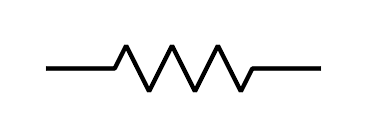
Like other parts of a circuit, a symbol is used to indicate resistance.